STM32F030F4P6 “AVR programmer” board
by Krzysztof Foltman
After the initial success with LPC810, I was ready to work on something with more memory and more I/O. Searching the Farnell catalogue for simple, low-cost and hobbyist-friendly MCUs, I found the tiny STM32F030F4P6 microcontroller made by ST Microelectronics.
The microcontroller
The chip is based on an ARM Cortex M0 core, has a 48 MHz clock, 16 KB ROM and 4 KB RAM and is available in a 20-pin 0.65mm TSSOP package.
Unlike the LPC chip, it provides plenty of I/O pins and a wider selection of peripherals, including SPI and timers. It is still an entry level chip. It has none of the advanced interfaces like USB or I2S present in its larger counterparts, but that gets reflected in price – it costs about 1.50 euro in single units.
The low price is particularly important for people without experience with soldering of relatively fine-pitch SMD packages – with some basic magnification they are not prohibitively difficult to solder, but getting a number of spares makes the whole learning process less stressful.
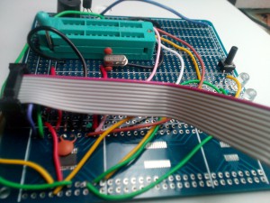
Several options are available to make sure that I would be able to use the new microcontroller. One of them involves using an SMD breakout board and a breadboard. However, I was skeptical of the ability to get the Serial Wire Debug programmer/debugger working with the breadboard – it usually requires fairly short wires and it is sensitive to signal quality issues. There is also the “dead bug” approach of gluing the IC upside down and soldering wires to it. This I rejected because of the soldering skills required. My easiest option involved using the first version of a 10x10cm matrix protoboard that arrived from China some time earlier.
Getting it working
After soldering the chip to the PCB, I needed a way to verify that it was working. The easiest way to achieve this was adding a decoupling capacitor and the SWD port, and using an STLink v2 programmer I got from Stijn to communicate with the chip. These programmers are easily available from eBay or Aliexpress, and work fine most of the time – the issues are usually resolved by holding the chip in reset manually. The example eBay link to get one of those programmers is Here
It took some trial-and-error to get adequate signal quality: long cables or having signal wires too close makes the communication unreliable at speeds that STLink is using. I found the correct configuration file to use with OpenOCD (32f0308discovery.cfg – it is included with OpenOCD).
Some time later, I had a working SWD set-up. On my system, and OpenOCD installed in /usr/local/, the example command to erase the flash and program an .elf file is:
sudo openocd -f /usr/local/share/openocd/scripts/board/32f0308discovery.cfg -c 'init' -c "program file.elf verify reset"
The next step involved writing a small program that blinks a LED, in order to make sure that the basics work. For this, I decided to use the code and the linker script for the LPC as a starting point. The memory addresses and the entire initialization code had to be changed to reflect the differences between platforms. And no more I2C or port expanders – this chip had enough I/O to do something that I could use in practice.
The project
At the time, I was trying to make a camera rail controller for a friend. It was meant to be a simple radio-operated stepper motor controller. That in itself could be a good opportunity to try a new microcontroller, if it wasn’t for the size constraints on the device. The 10x10cm prototyping board was too large to fit in the carriage of the device, and the smaller prototyping board was through-hole only. Also, the project didn’t really require a lot of processing power, an ATmega chip would work equally well.
A project based on ATmega is probably easiest to prototype using Arduino environment. But it’s not like it’s easy to buy an ATmega with bootloader burned in, at least in Ireland – it might involve a few days of waiting or paying a good chunk of money for an original Arduino from Maplin just to source the chip. So, what if I built a device to do exactly that – to take a blank ATmega and burn the Arduino bootloader into it. Sounds like a nice learning project to use the STM32 for!
 The STM32 definitely had enough I/O pins and memory, and an SPI peripheral that could be used for communicating with the AVR In-Circuit Serial Programming port. The board had enough space to host a 28-pin ZIF socket, so I added that and some user interface elements – two LEDs (green and red) with suitable resistors and a reset button. The SPI-based ICSP code was easy enough to write based on Atmel’s documentation: the datasheet and the AVR910 application note about using the programming interfaces. Finding the correct version of the Arduino bootloader was slightly harder than I expected, but I had it all working after a single afternoon of coding. The slightly cleaned up version of the code and very rough documentation is available here
The remaining parts are:
- the clock crystal and the load capacitors for the ATmega – but not for the STM32 as it runs off its own internal RC clock
- the beeper – not strictly required but a nice addition. I didn’t dare to power the beeper directly from the microcontroller, so I used an 2N3904 transistor in common emitter mode as a switch.
The programmer code checks the device ID and uploads the bootloader, sets the correct fuses and then uploads a blinky example.
Now, any time I want to make a simple device based on an ATmega microcontrolller, I don’t need to buy a pre-programmed chip – I can get a blank one and pre-program it by simply inserting the chip into the board’s ZIF socket and press a button. After a while, I get a long “beep” and a green light, announcing the fact that the chip is functional and ready to use. Even better, this board provides a simple way to check an Atmega chip that I suspect to be damaged during one of my failed experiments: a series of beeps and a red light will remove any doubt.
Summary
This Is Not Rocket Science at all.
The tricky parts is soldering and SWD signal quality, and the initialization and the linker script. One needs to remember to enable all the clocks during start-up and to take care of the interrupts. Otherwise, there may be unexpected crashes when SysTick gets triggered and there is no ISR to call. Overall, this chip is easy to obtain (Farnell), inexpensive, relatively easy to use and less limited than the 8-pin LPC chip.
There are some comparable options from other manufacturers in the same market segment: LPC811 and LPC812 from NXP (the latter is also available in a 20-pin SOIC package with 1.27mm pin pitch, making it easier to solder). My preferred option was an STMicro part because of my prior experience with their Discovery boards and the fact that most of skills learned when working with a specific microcontroller are usable across their entire chip lines. Most of the time they use the same peripheral, so parts of the code can often be ported -with minimal changes- to their 180 MHz parts. NXP parts have several other advantages, the most important being the clear documentation they provide and their very flexible pin assignment matrix.


